A wet scrubber is designed to remove gaseous or contaminated particles from a gas flow. Figure 2 shows the diagram of a packedbed ... resistivity in the electrostatic precipitation process. In combustion of coal, ... an electrostatic precipitator (ESP) of a coal based power plant. In: 6th BSME International Conference on Thermal Engineering ...
WhatsApp: +86 18037808511
Process model of the Coalfired Power Plant Source: (CoalFired Power Station, Diagram Stock Image C024/7686, ) ... singleflow turbine with axial exhaust is achievable by using a longer ...
WhatsApp: +86 18037808511
Process flow diagram of conventional postcombustion CO 2 ... A conventional coalfired power plant with postcombustion capture has to separate carbon dioxide from a flue gas mixture in which there is a large amount of nitrogen. The oxyfuel process, by removing the nitrogen at the start, so that coal burns in oxygen instead of air, sidesteps ...
WhatsApp: +86 18037808511
A coalfired power station or coal power plant is a thermal power station which burns coal to generate electricity. Worldwide there are over 2,400 coalfired power stations, totaling over 2,000 gigawatts capacity. [1] They generate about a third of the world's electricity, [2] but cause many illnesses and the most early deaths, [3] mainly from ...
WhatsApp: +86 18037808511
Energyefficient Technologies in Direct Reduction of Iron Process 17 Waste Heat Recovery for Power Generation 18 Iron Ore Preheating Rotary Kiln Using Waste Heat Recovery System 20 Coal Gasification for Partial Substitution in Rotary Kiln 22 Waste Heat Recoverybased Absorption Chiller 23
WhatsApp: +86 18037808511
Carbon Capture and Storage A technology which reduces carbon emissions from the combustion based power generation process and stores it in a suitable location ... Process Flow Diagram Process Flow Diagram (PFD) is a drawing which describesthe process flow for a processing plant. PFD is used to capture the main process equipment
WhatsApp: +86 18037808511
The results indicate that cofiring 10% of biomass in a coalbased power plant only slightly affects the energy performance of the plant, reducing the net efficiency by % points. ... A simplified process flow diagram of the MEAbased chemical absorption process for CO 2 capture used in this study is shown in Figure 4.
WhatsApp: +86 18037808511
Methanol is a clean fuel and an important feedstock for the petrochemical industry. Conventionally, the coaltomethanol process generates a substantial amount of CO2 emissions with a low yield of methanol. In this study, we propose the conceptual design development of coaltomethanol process using captured CO2 from the gasification plant by implying process intensification. The base case and ...
WhatsApp: +86 18037808511
SmallScale Flexible Advanced UltraSupercritical CoalFired Power Plant with Integrated Carbon Capture ... Coal Based Power Plants of the Future Project Execution Plan March 26, 2020 U. S. Department of Energy. Contract: CFE000023 (Mod. 004) ... • Process Flow Diagrams • Heat and Material Balance • Equipment List(s) • Utility ...
WhatsApp: +86 18037808511
The diagram below shows the position of an ESP within a coal fired power station flue gas system. Another important component used for flue gas cleaning is the flue gas desulphuriser (FDG), also referred to as a 'scrubber tower'; the scrubber tower is shown to the left of the ESP on the below diagram. Flue Gas System With ESP Highlighted
WhatsApp: +86 18037808511
A process flow diagram of the proposed power plant layout is shown in Fig. 10. Based on mass and energy balances discussed in the "Layout of natural gasfired pressurized CLC" and "Layout of syngas fired pressurized CLC" sections, this has been developed for a 761 MW th plant when fired with natural gas and 800 MW th when fired with ...
WhatsApp: +86 18037808511
Oil is occasionally used to generate electricity as well. Figure n : This combustion chamber burns either natural gas or oil. Fuel flows through a natural gas line or from oil storage into the combustion chamber. Air passes through the air intake and is compressed in the compressor.
WhatsApp: +86 18037808511
As this diagram shows, the plant operates on the same principles as other fossilfueled electric generating plants—it burns coal to produce heat that turns water into steam, which then turns turbines in a generator. Sources/Usage: Public Domain. Credit: Georgia Power
WhatsApp: +86 18037808511
The application of oxyfuel combustion for coal fired power plant could be broadly classified according to: (a) oxyPC and (b) oxyCFB. On the other hand, the application of oxyfuel combustion for gas turbine based power plant could be broadly classified according to its working fluid namely: (a) CO 2 based GT cycles and (b) Water based GT cycles.
WhatsApp: +86 18037808511
Working Principle of a Thermal Plant. The working fluid is water and steam. This is called feed water and steam cycle. The ideal Thermodynamic Cycle to which the operation of a Thermal Power Station closely resembles is the RANKINE CYCLE.. In a steam boiler, the water is heated up by burning the fuel in the air in the furnace, and the function of the boiler is to give dry superheated steam at ...
WhatsApp: +86 18037808511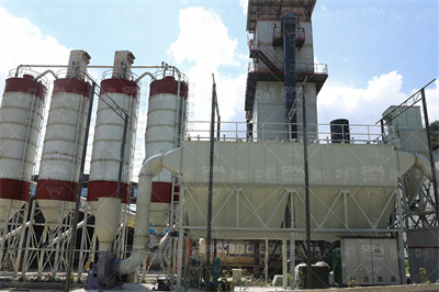
Like any thermal power station, we generate electricity from steam. Our entire process can be simplified into four main steps: Fuel is burned to create heat. By using finely pulverized coal, efficient combustion is assured and high temperatures are achieved. The heat is applied to demineralized water inside the boiler, turning it into steam.
WhatsApp: +86 18037808511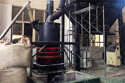
CEATETDCHP001 Typical coal flow diagrams for 2 x 500MW thermal power plant (with ... A coal based thermal power plant consists of large number of integrated plants/systems and equipment having mechanical, electrical, instrumentation control and civil components. The plant systems and equipment can be broadly classified into following
WhatsApp: +86 18037808511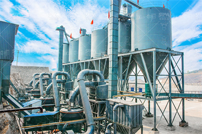
The Kemper County IGCC power plant consists of two islands, the gasification island and the power island. Fig. shows a simplified block flow diagram of the overall process for easy reading; whereas, a more detailed block flow diagram is displayed in Fig. The overall layout characteristics of the facility include:
WhatsApp: +86 18037808511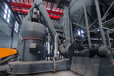
Integrated Gasification Combined Cycle (IGCC) is a power generation technology in which the solid feedstock (coal, lignite, biomass etc.) is partially oxidized with oxygen and steam to produce syngas. In a conventional IGCC design for power generation without carbon capture, the syngas is purified for dust and hydrogen sulphide removal and then ...
WhatsApp: +86 18037808511
Coal and oilfired process. Coal and oilfired steam power plants have steam turbines to convert the heat energy of combustion into mechanical energy, which then operates an electric generator. All plants use the steam turbine for the drop between the high pressure and temperature of the steam and the lower pressure of condensing vapor.
WhatsApp: +86 18037808511
How a Coal Plant Works. Coalfired plants produce electricity by burning coal in a boiler to produce steam. The steam produced, under tremendous pressure, flows into a turbine, which spins a generator to create electricity. The steam is then cooled, condensed back into water and returned to the boiler to start the process over. Here's a real ...
WhatsApp: +86 18037808511
Investigation of aerosol and gas emissions from a coalfired power plant under various operating conditions. The concentrations of fine particles and selected gas pollutants in the flue gas ...
WhatsApp: +86 18037808511
Process flow diagram of the considered power plant. Download : Download highres image (652KB) Download : ... Exergy analysis and heat integration of a coalbased oxycombustion power plant. Energy Fuels, 27 (2013), pp. . CrossRef View in Scopus Google Scholar. Goodarzi, 2021.
WhatsApp: +86 18037808511![Gas Turbine Power Plant: Diagram, Working Types [PDF]](/xpvza9k/6.jpg)
Advantages of Gas Turbine Power Plant with Nuclear Power Plant. The following are the advantages of a gas turbine power plant with a nuclear power plant: Low weight and size: wt of the plant per kW output is low. Any hydrocarbon fuel from highoctane gasoline to heavy diesel oil can be used efficiently. Easy startup and shutdown.
WhatsApp: +86 18037808511
Coalfired power plant. This study focuses on a coalfired power plant with a 700 MW supercritical tangential firing boiler built in the Kansai region of Japan and is operated using mixtures of various types of coal in consideration of economic efficiency. Figure 1 shows a schematic diagram of the overall system configuration (Zhang. (2013)).
WhatsApp: +86 18037808511
Simplified process flow diagram of the water steam cycle of a power plant (Wellner et al., 2016). ... The modeled power plant is based on the coal fired single block supercritical power plant with a 920 MW gross electric output located in Heyden, Germany. During the modeling process, several simplifications were made to allow for a fast ...
WhatsApp: +86 18037808511
Narula illustrated that, due to the addition of CO 2 amine scrubbers at the back end of the power plant to reduce CO 2 emissions, the net plant output decreases by about 25 percent from 2 x 400 to ...
WhatsApp: +86 18037808511
sufficient coal reserves available to keep the power station in operation should the mine experience production problems. Inside the power station, the coal is pulverised to a fine powder in giant grinding mills. This is because pulverised coal burns quickly, like gas. The pulverised coal is transported to the boiler furnace with air where it ...
WhatsApp: +86 18037808511
A simplified layout of a thermal power station is shown below. Coal: In a coal based thermal power plant, coal is transported from coal mines to the generating station. Generally, bituminous coal or brown coal is used as fuel. The coal is stored in either 'dead storage' or in 'live storage'. Dead storage is generally 40 days backup coal storage ...
WhatsApp: +86 18037808511
1 Scope. This part of ISO 14084 specifies types of process diagrams for power plants and rules and guidelines for the preparation and representation of information in such diagrams. This part of ISO 14084 series is a collective application standard of the ISO 15519 series. This part of ISO 14084 does not apply to electrotechnical diagrams ...
WhatsApp: +86 18037808511
Stage 1 The first conversion of energy takes place in the boiler. Coal is burnt in the boiler furnace to produce heat. Carbon in the coal and Oxygen in the air combine to produce Carbon Dioxide and heat. Stage 2 The second stage is the thermodynamic process. The heat from combustion of the coal boils water in the boiler to produce steam.
WhatsApp: +86 18037808511
Below is a schematic flow diagram of an IGCC plant: Block diagram of IGCC power plant, which utilizes the HRSG The gasification process can produce syngas from a wide variety of carboncontaining feedstocks, such as highsulfur coal, heavy petroleum residues, and biomass .
WhatsApp: +86 18037808511
Library. Typical IGCC Configuration. Figure 1 depicts the overall process configuration of a notable IGCC power generation unit located in the United States, the TECO Polk Power Plant Unit 1. This unit is quite representative of IGCC plants in general; further information is provided on the dedicated page for the Tampa Electric IGCC project .
WhatsApp: +86 18037808511
A material supplier from Belgium would like to produce limestone powder for his custome...

India is rich in various mineral resources and it is an important mineral processing market
Copyright © 2023 GMC Co., Ltd. SiteMap

