The distance between the outside circle of a gear and the root circle of its mating gear (the gap) is called the root clearance. This distance (the gap) is also called the root clearance, top clearance, bottom clearance or simply the clearance.
WhatsApp: +86 18037808511
Our gears with ratio 222/27 ahs a diameter of more than 5m. b) Take care of the profile machiining the root radius etc should not be damaged during hobbing the involute. I saw in an article the tip clearance should be between to of the module for our module of 27 it is between to
WhatsApp: +86 18037808511
The gear box is a setup intended for making the power transmission from the electric motor to the ball mill. During this stage the gear box plays a crucial role in terms of controlling speed and torque. The gear box is a collection of shafts, bearings, casing and gears in a systematic form to obtain the desired output.
WhatsApp: +86 18037808511
Before the drive train can engage the load and transmit torque, the gears must close this gap. If these gaps become too large, however, the gearbox introduces the kind of lost motion we've been discussing. In the case of couplings, compliance can appear as backlash and can introduce a wind up before the load moves.
WhatsApp: +86 18037808511
• Gear blank deflections. ... and the backlash increases from in to in. Misalignment Slope at 4000 inlb. ... root stresses, and many other design evaluation parameters. Figure 10 shows the contact stresses for both the aligned and misaligned perfect involute helical gears whose load distribution is shown in Figure 4.
WhatsApp: +86 18037808511
Dialing It In. Once fully seated, install and tighten down the carrier pads. Always install and tighten the right side first. With the carrier assembly installed, attach your dial indicator with the plunger at a 90degree angle from the face of the ring gear teeth. Gently rock the carrier back and forth to measure your backlash.
WhatsApp: +86 18037808511
Contribute to zhosuren/es development by creating an account on GitHub.
WhatsApp: +86 18037808511
#cementfactory #rootclearence#backlash#Module#formula #girth gear#formula for root clearance#formula for Backlash#formula for module#gear #gear terminology
WhatsApp: +86 18037808511
® Ring Gear • Installation Manual (Page 17 of 31) are tangent or operating apart. If scribe lines overlap, as in case NOTE: In some cases ( when the drive components are 3, it is necessary to separate the gear and pinion to provide aligned), it may be easier to move the shell as opposed to the necessary backlash. pinion pillow blocks.
WhatsApp: +86 18037808511
2. Adjustment of ball mill girth gear. According to the specification requirements: the radial runout of the large ring gear, the diameter of the pitch circle per meter should not exceed ; the end face of the large ring gear beats, the diameter of the pitch circle per meter should not exceed If it is out of tolerance, it needs to ...
WhatsApp: +86 18037808511
how to calculate girth gear root clearance Formulas for gear calculation What is the standard root clearence and backlash of . SPUR GEARS Worm Gears Agro Engineers Helical Gear
WhatsApp: +86 18037808511
During finish milling process of the spiral bevel gear (X40 steel) with a ballend mill cutter (HSLB2030), the parameter that has most influence on F was spindle speed ( %).
WhatsApp: +86 18037808511
Spur gear terminology. Design considerations for a gear. In designing and analyzing a gear the following data is required: The power to be transmitted. The maximum torque on the system. The speed of pinion (or driving gear) usually given in RPM. The speed of driven gear. The Centre distance between gears.
WhatsApp: +86 18037808511
The main gear is cut from a special gear steel casting and is made split and reversible. The pinion, usually integral with the pinion shaft, is cut from an alloy steel forging and heat treated prior to cutting the teeth. The pinion shaft is double ended so it is also reversible. All ball Mill gearing is designed in accordance with sound ...
WhatsApp: +86 18037808511![What is backlash in measurement? [Ultimate Guide!] Physics Network](/xpvza9k/66.jpg)
The Gear box backlash is the clearance or gap between the two mating gear tooth. The backlash can be measured with dial gauge, feeler gauge or lead wire. The Dial Gauge pointer is kept at Driven gear face and the drive gear is locked. Then the driven gear is moved which shows the backlash valve in the dial gauge.
WhatsApp: +86 18037808511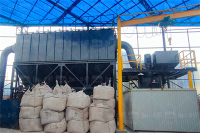
of girth gear, pinions and drives. Repair and refurbishment Our repair and refurbishment team provides handson gear service including: Temporary repairs of crack and wear on girth gear and pinion Ball mill flange runout machining. Inspection services Beside the visual inspection of girth gears we also apply: Radial and axial runout ...
WhatsApp: +86 18037808511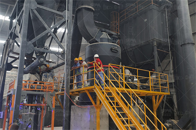
The DMG2 gear units cover the entire power range from 1,200 to 10,000 kW in standalone operation and up to 20,000 kW with the use of a dual drive. Worldwide, over 400 of these large gear units have already been deployed successfully. Your benefits at a glance. Compact and efficient drive. More effective use of the girth gear.
WhatsApp: +86 18037808511
You've already forked sbm 0 Code Issues Pull Requests Packages Projects Releases Wiki Activity
WhatsApp: +86 18037808511
For example, if we have a gear with a 1 DP, FHD tooth form, 150 in. center distance, and an anticipated 90F temperature rise above ambient, the required root clearance would be: Tooth Form Root Clearance Thermal Backlash Root Clearance Requirement: Proceed to Step .272 in. + .090 in. = .362 in. 638110 May 1999 Supersedes 1197
WhatsApp: +86 18037808511
Ball Mill Inspection Overview The following report provides a brief overview of the Ball mill inspection conducted on 18th February 2015 The gearing terminology is based on the AGMA 1010E95 standard, "Appearance of Gear Teeth" Pinion tooth measurements were recorded on both pinions. It should be noted that these measurements have low reproducibility and are for "general reference ...
WhatsApp: +86 18037808511
Size measurement is used to provide the correct backlash when the gear is mounted with its mating gear at operating center distance. Measurement of size with micrometer and pins or balls (Figure 1). Figure 1: Measurement of size with micrometer and pins or balls. Measurement of size with tooth caliper (Figure 2).
WhatsApp: +86 18037808511
Cleaning of gear ring and mill flange → positioning of gear ring → coarse alignment of large gear ring → positioning and coarse alignment of pinion → installation of motor reducer → primary grouting → fine alignment of large gear ring → fine alignment of pinion → fine alignment of motor reducer. 02 alignment of girth gear (big gear)
WhatsApp: +86 18037808511
A material supplier from Belgium would like to produce limestone powder for his custome...

India is rich in various mineral resources and it is an important mineral processing market
Copyright © 2023 GMC Co., Ltd. SiteMap

